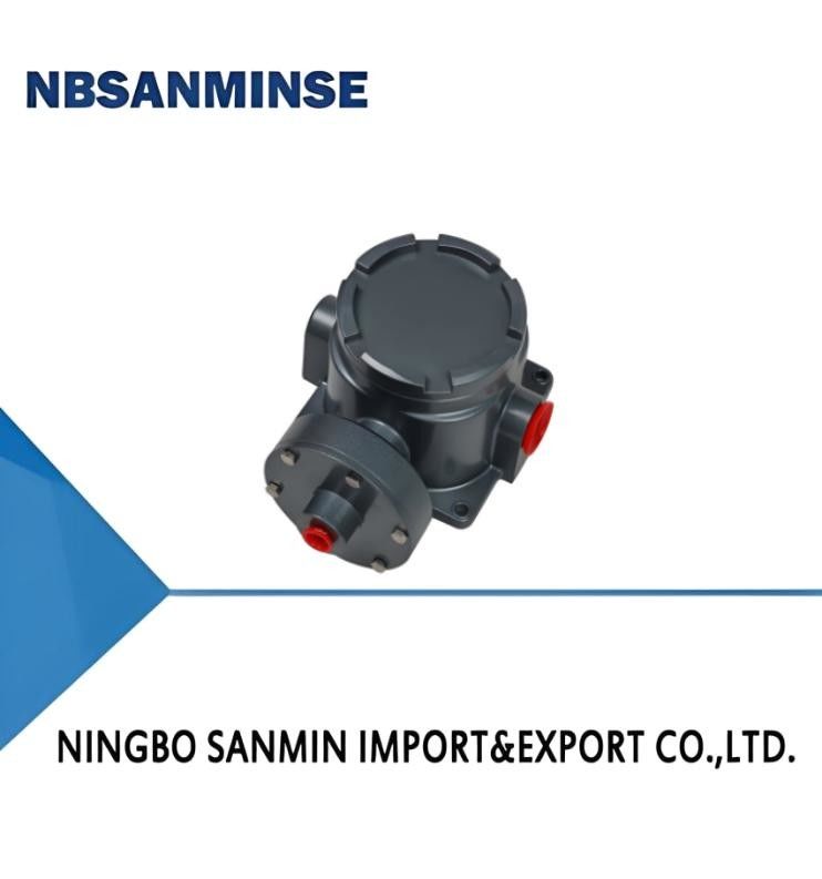
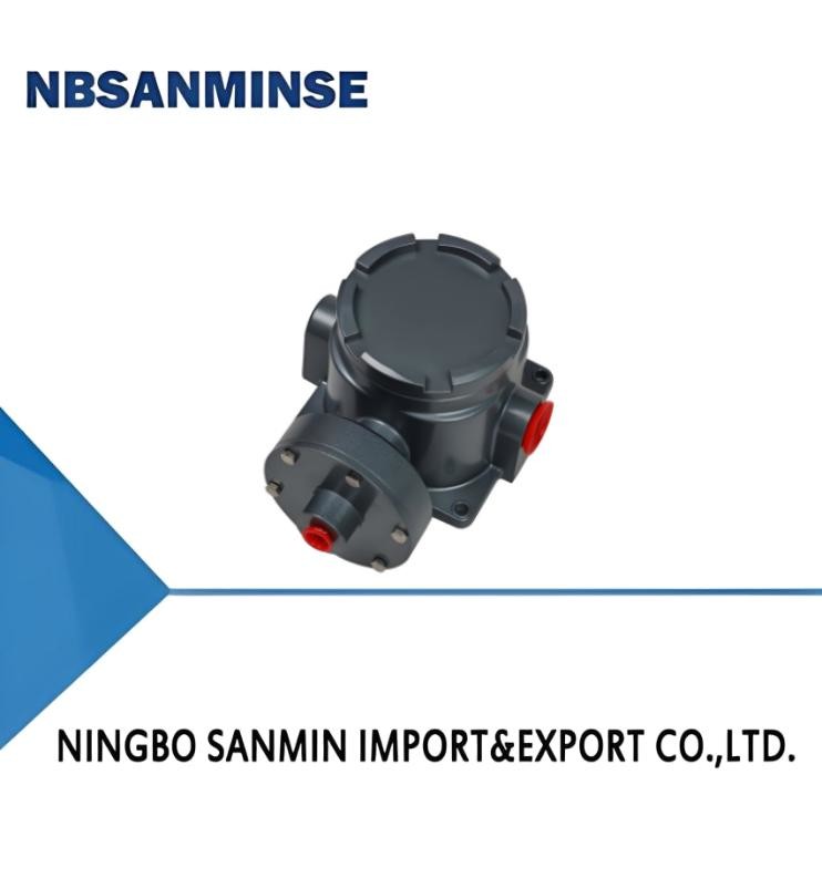
TL5228 Marine Pressure Switch Pressure Controller
Contact Person : Ina Chen
Phone Number : 0086-15168536055
WhatsApp : +8615168536055
Detail Information |
|||
Switching Element: | Microswitch | Ambient Temp.: | -40℃~60℃ |
---|---|---|---|
Medium Temp.: | 0~80℃ | Repeatability Error: | 0.5% Or 1% |
Product Description
1, Overview
The working principle of TXK explosion-proof pressure controller is mainly based on the elastic deformation of test components (such as diaphragms), which drives functional components (such as micro switches) to produce rapid switch jumping actions through this deformation. Specifically, when the pressure of the measured (controlled) medium is applied to the testing element, it will cause the free end of the diaphragm to produce corresponding elastic displacement. This displacement will then drive the button (push rod) in the micro switch connected to the pipe end to produce corresponding actions. When the pressure reaches the set control value, the switch contacts will switch, causing the circuit in the control system to disconnect or connect, thereby achieving the purpose of automatic control and signaling.
TXK explosion-proof pressure controller usually consists of a measurement system, control device, adjustment mechanism, housing, plug socket, etc. The diaphragm in the measurement system senses pressure changes through its elastic deformation, while the micro switch in the control device quickly responds to this pressure signal and performs circuit on/off operations. This design enables the explosion-proof pressure controller to operate stably in various industrial environments, especially in applications that require high reliability and safety.
2, Technical performance
Working viscosity |
<1 × 10⁻³m2/s |
Medium temperature |
0~80℃ |
Switching element |
microswitch |
Anti-Vibration Performance |
20m/s2 |
Dust explosion-proof level |
Exdb Ⅱ CT4~T6 Gb |
Explosion proof certificate number |
GYB24.2900X |
Degrees of protection provided by enclosure |
IP66(Compliant with DIN40050 and equivalent to IP66 in GB4208) |
Repeatability error |
0.5% or 1% |
Ambient temperature |
-40℃~60℃ |
Contact capacity |
AC 220V 6A(Resistive) |
3, Specifications
|
|
|
External dimensions |
|
Membrane material |
|
-100~0KPa |
2KPa |
1.3 |
03 |
30 |
Stainless steel or polyimide |
NPT1/4 |
-100~ 100KPa |
2KPa |
1.3 |
02 |
30 |
Stainless steel or polyimide |
NPT1/4 |
0~ 100KPa |
2KPa |
1.3 |
03 |
30 |
Stainless steel or polyimide |
NPT1/4 |
5~ 170KPa |
2KPa |
1.3 |
02 |
30 |
Stainless steel or polyimide |
NPT1/4 |
5~210KPa |
4.5KPa |
1.3 |
01 |
30 |
Stainless steel or polyimide |
NPT1/4 |
10~350KPa |
3KPa |
1.3 |
02 |
30 |
Stainless steel or polyimide |
NPT1/4 |
20~700KPa |
12KPa |
5 |
01 |
30 |
Stainless steel or polyimide |
NPT1/4 |
0.15~ 1.2MPa |
0.02MPa |
5 |
01 |
30 |
Stainless steel or polyimide |
NPT1/4 |
0.25~2.5MPa |
0.04MPa |
5 |
01 |
30 |
Stainless steel or polyimide |
NPT1/4 |
0.37~3.7MPa |
0.08MPa |
6 |
01 |
30 |
Stainless steel or polyimide |
NPT1/4 |
0.7~7MPa |
0. 12MPa |
9 |
01 |
30 |
Stainless steel or polyimide |
NPT1/4 |
1.2~ 12MPa |
0. 15MPa |
17.5 |
01 |
30 |
Stainless steel or polyimide |
NPT1/4 |
3.5~27.5MPa |
1MPa |
34 |
01 |
30 |
Stainless steel or polyimide |
NPT1/4 |
4, Selection Table
TXK - □ □ - □ - □ - □ 1 2 3 4 5 |
|||||
1. Product Form |
|||||
01 |
convention |
02 |
double-contact |
03 |
EEx d |
04 |
Lower differential pressure |
05 |
Upper and lower differential pressure |
06 |
High hydrostatic pressure |
07 |
furnace |
||||
2. Shell |
|||||
NN |
Regular style |
RN |
Dual contact model |
LC |
Ordinary explosion-proof model |
B |
Explosion proof model with small viewing window |
AL |
Furnace shell |
||
3. Diaphragm type |
|||||
01 |
poly |
02 |
stainless steel |
03 |
rubber |
4. Connecting thread (customizable as needed) |
|||||
01 |
NPT1/4 内 |
||||
5. Range |
Refer to the range comparison table |
||||
TXK explosion-proof controller, product form: explosion-proof, shell: ordinary explosion-proof type, diaphragm form: stainless steel, connection thread: NPT1/4 internal, range: 0.25-2.5MPa. |
Range comparison table
code |
range |
notes |
code |
range |
notes |
001 |
3.5-27.5MPa |
Conventional pressure |
002 |
1.2-12MPa |
Conventional pressure |
003 |
0.7-7MPa |
Conventional pressure |
004 |
0.37-3.7MPa |
Conventional pressure |
005 |
0.25-2.5MPa |
Conventional pressure |
006 |
0.15-1.2MPa |
Conventional pressure |
007 |
20-700KPa |
Conventional pressure |
008 |
10-350KPa |
Conventional pressure |
009 |
5-210KPa |
Conventional pressure |
010 |
5-170KPa |
Conventional pressure |
011 |
0-100KPa |
Conventional pressure |
012 |
﹣100-0KPa |
Conventional pressure |
013 |
﹣100-100KPa |
Conventional pressure |
014 |
25KPa |
High hydrostatic pressure |
015 |
0-60KPa |
Lower differential pressure |
016 |
20-200KPa |
Lower differential pressure |
017 |
50-500KPa |
Lower differential pressure |
018 |
﹣0.5-0.5KPa |
Furnace differential pressure |
019 |
﹣3-3KPa |
Furnace differential pressure |
020 |
﹣6-6KPa |
Furnace differential pressure |
021 |
﹣12-12KPa |
Furnace differential pressure |
5, Debugging method and switch wiring diagram
Return the adjusting nut to a state of basic weakness, connect the C, NO, NC wires of the switch to the signal light. Observe the status of the signal light, connect the signal light to a green light (C is the common terminal, and when C and NO are connected at the factory, the green light will turn on), and adjust the adjusting nut up and down according to the set point indicator to set it to the desired set point. (The downward pressure increases, the upward pressure decreases)
6, Appearance and installation dimensions
01
02
03
Enter Your Message