|
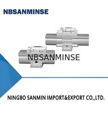
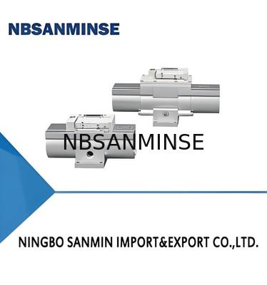
Product Details:
|
Material: | Aluminum | Pressure: | 1.0MPA |
---|---|---|---|
Port Size: | Rc1/4"、Rc1/2" | Working Pressure: | 0.15-0.8Mpa,0-7kgf/cm3 |
Working Temperature: | 5-50degree,5~50°C | Application: | Automatic Pressure Relief Protection Device |
Highlight: | energy saving pneumatic solenoid valve,compact booster regulator valve,VBA series solenoid regulator |
VBA | 10A | 02 | □ | X3145 | ||
Specification oode | Valve Body size | Port size | Option | |||
10A:1/4 Standard | 02:RC 1/4" | Symbol | Accessories | Suitableforvalvebodysize | ||
20A:1/2Standard | 04:RC1/2" | Nil |
None |
10A,20A | ||
G | OUT side pressure gauge | 10A,20A | ||||
B | Gas cylinder Installation bolts | 20A | ||||
GB |
OUT side pressure gauge+ Gas cylinder installation' bolts |
20A |
Standard Specifications | Model | VBA10A-02 | VBA20A-03 | VBA40A-04 | VBA22A-03 | VBA42A-04 | VBA43A-04 | VBA11A-02 |
---|---|---|---|---|---|---|---|---|
Fluid Used | multicolumn{7}{c}{Compressed Air} | |||||||
Pressure Ratio | multicolumn{5}{c}{2 times} | multicolumn{2}{c}{2–4 times} | ||||||
Pilot Function | multicolumn{3}{c}{With pilot function
|
multicolumn{2}{c}{Air-operated type} | multicolumn{2}{c}{With pilot function
|
|||||
Pressure Adjustment Mechanism | multicolumn{3}{c}{1000} | 1000 | 1000 | 1000 | 70 | |||
Maximum Flow Rate <sup>(5)</sup> (L/min(ANR)) | 230 | 1000 | 1000 | 1000 | 1000 | 1000 | 70 | |
Set Pressure Range (MPa) | 0.2–2.0 | 0.2–1.0 | 0.2–1.0 | 0.2–1.0 | 0.2–1.6 | 0.2–2.0 | 0.2–2.0 | |
Minimum Pressure Range (MPa) | multicolumn{3}{c}{—} | 0.1–1.0 | multicolumn{2}{c}{2–4} | — | ||||
Proof Pressure (MPa) | 3 | 3 | 3 | 1.5 | 2.4 | 3 | 3 | |
Connection Size (IN, OUT, EXH ports) (Rc) | 1/4 | 3/8 | 1/2 | 3/8 | 1/2 | 1/2 | 1/4 | |
(IN/OUT 2 ports) (Rc) | multicolumn{3}{c}{—} | multicolumn{3}{c}{1/8} | — | |||||
Ambient Temperature and Fluid Temperature in Use (°C) | multicolumn{6}{c}{2–50 (No freezing)} | — | ||||||
Mounting Method | multicolumn{7}{c}{Horizontal} | |||||||
Lubrication | multicolumn{7}{c}{Oil-free (No lubrication)} | |||||||
Mass (kg) | 0.84 | 3.9 | 8.8 | 3.9 | 8.6 | 8.6 | 0.89 |
Assuming an intake pressure of 0.5MPA and a required boost to 0.8MPA, with an average air flow rate of 500L/Min, based on the boost ratio and pre selected flow rate of VBA20A, comparing the flow characteristics of 20A, the intake P1=0.5MPA. When the air consumption is equal to 500L/MIN, the intake pressure is around 0.85MPA, which is higher than the predetermined 0.8MPA and meets the design requirements. Therefore, the VBA20A model is selected for use
Assuming that the intake pressure is 0.5MPA, it is required to increase the pressure to 0.8MPA, and the average air flow rate is 50OL/Min. The outlet pressure should not fluctuate
Based on the selection results of Example 1, the VBA20A model was chosen because the booster valve is based on the piston type boosting principle, and the outlet pressure will have periodic pulsation. Therefore, a small air storage tank was selected to filter the pulsation. Since there are no special requirements, the air storage tank can be selected based on the on-site situation. Now, a 10L air storage tank is selected as the matching tank
Other selection cases
If the booster valve is used for periodic gas consumption, or if there are requirements for inflation time when inflating sealed containers, you can contact customer service for assistance in selection reference
The function of gas cylinders
Relieve pressure fluctuations at the outlet of the pressure boosting valve
In situations where intermittent movements cause air consumption to exceed supply capacity, concentration can be used
The amount of air consumed is stored in a gas tank for use. If it is caused by continuous actions
If the air consumption exceeds the supply capacity, using gas cylinders will not be effective.
Precautions for using gas cylinders
one
An oil mist separator needs to be installed on the side near the booster valve. If the quality of compressed air is not guaranteed, it will result in poor operation of the booster valve (unable to boost) and reduced durability.
two
In situations where dry air is used (atmospheric dew point below 17C), the lifespan may be shortened due to the evaporation of internal lubrication.
three
The supply on the inlet side is approximately 2 times (boost ratio 2) or 4 times (boost ratio 4) the usage on the outlet side, as the boost valve is powered by air pressure. Therefore, the supply on the inlet side should be the sum of the flow rate on the outlet side and a portion of the discharge from the E port.
four
The setting of export pressure should be more than 0.1MPA higher than the inlet pressure. If the pressure difference is below 0.1MPA, it will cause unstable movement and poor movement.
Contact Person: Ina Chen
Tel: 0086-15168536055
Fax: 86-574-88915660