

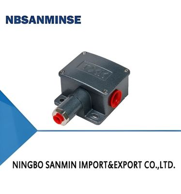
TL5228 Marine Pressure Switch Pressure Controller

Contact Person : Ina Chen
Phone Number : 0086-15168536055
WhatsApp : +8615168536055


| Place of Origin: | CHINA | Brand Name: | NBSANMINSE |
|---|---|---|---|
| Certification: | CE | Model Number: | TXK |
|
Detail Information |
|||
| Switching Element: | Microswitch | Ambient Temp.: | -20℃-60℃ |
|---|---|---|---|
| Medium Temp.: | 0℃-80℃ | Repeatability Error: | 1%or0.5% |
Product Description
![]()
1, Overview
TXK pressure switch is a reliable on-site installation instrument. The piston spring diaphragm combination structure adopts a static O-ring seal, which has excellent seismic and overpressure resistance, as well as small backlash and wide measurement range. Widely used in industries such as petroleum, chemical, thermal power, thermoelectric, metallurgy, pharmaceuticals, etc. Its coverage range is -0.1MPa~27.5MPa.
2, Technical performance
|
Working viscosity |
1x10⁻³m2/s |
|
Switching element |
microswitch |
|
Enclosure ratings |
IP65 |
|
Ambient temperature |
-20℃-60℃ |
|
Medium temperature |
0℃-80℃ |
|
Anti-Vibration Performance |
40m/s² |
|
Repeatability error |
1%or0.5% |
|
Contact capacity |
Max 220V AC, ≤5A |
3, Specifications
|
Adjustment range of pressure setting value
|
Switching difference not greater than
|
**Allowable pressure (Mpa)
|
External dimensions |
Switching frequency/minute
|
Membrane material |
Internal thread of interface
|
|
-100~0KPa |
3KPa |
1.3 |
03 |
30 |
Stainless steel or polyimide |
NPT1/4 |
|
-100~100KPa |
3KPa |
1.3 |
02 |
30 |
Stainless steel or polyimide |
NPT1/4 |
|
0~100KPa |
3KPa |
1.3 |
03 |
30 |
Stainless steel or polyimide |
NPT1/4 |
|
5~170KPa |
2KPa |
1.3 |
02 |
30 |
Stainless steel or polyimide |
NPT1/4 |
|
5~210KPa |
5KPa |
1.3 |
01 |
30 |
Stainless steel or polyimide |
NPT1/4 |
|
10~350KPa |
4KPa |
1.3 |
02 |
30 |
Stainless steel or polyimide |
NPT1/4 |
|
20~700KPa |
15KPa |
1.5 |
01 |
30 |
Stainless steel or polyimide |
NPT1/4 |
|
0.15~1.2MPa |
0.02MPa |
3 |
01 |
30 |
Stainless steel or polyimide |
NPT1/4 |
|
0.25~2.5MPa |
0.04MPa |
5 |
01 |
30 |
Stainless steel or polyimide |
NPT1/4 |
|
0.37~3.7MPa |
0.08MPa |
6 |
01 |
30 |
Stainless steel or polyimide |
NPT1/4 |
|
0.7~7MPa |
0.12MPa |
10 |
01 |
30 |
Stainless steel or polyimide |
NPT1/4 |
|
1.2~12MPa |
0.15MPa |
17.5 |
01 |
30 |
Stainless steel or polyimide |
NPT1/4 |
|
3.5~27.5MPa |
1MPa |
34 |
01 |
30 |
Stainless steel or polyimide |
NPT1/4 |
4, Selection Table
|
TXK - □ □ - □ - □ - □ 1 2 3 4 5 |
|||||
|
1. Product Form |
|||||
|
01 |
convention |
02 |
double-contact |
03 |
EEx d |
|
04 |
Lower differential pressure |
05 |
Upper and lower differential pressure |
06 |
High hydrostatic pressure |
|
07 |
furnace |
||||
|
2. Shell |
|||||
|
NN |
Regular style |
RN |
Dual contact model |
LC |
Ordinary explosion-proof model |
|
B |
Explosion proof model with small viewing window |
AL |
Furnace shell |
||
|
3. Diaphragm type |
|||||
|
01 |
poly |
02 |
stainless steel |
03 |
rubber |
|
4. Connecting thread (customizable as needed) |
|||||
|
01 |
NPT1/4 内 |
||||
|
5. Range |
Refer to the range comparison table |
||||
|
TXK pressure controller, product form: regular, shell: regular, diaphragm form: stainless steel, connection thread: NPT1/4 internal, range: 3.5-27.5MPa. |
|||||
Range comparison table
|
Code |
Range |
Notes |
Code |
Range |
Notes |
|
001 |
3.5-27.5MPa |
Conventional pressure |
002 |
1.2-12MPa |
Conventional pressure |
|
003 |
0.7-7MPa |
Conventional pressure |
004 |
0.37-3.7MPa |
Conventional pressure |
|
005 |
0.25-2.5MPa |
Conventional pressure |
006 |
0.15-1.2MPa |
Conventional pressure |
|
007 |
20-700KPa |
Conventional pressure |
008 |
10-350KPa |
Conventional pressure |
|
009 |
5-210KPa |
Conventional pressure |
010 |
5-170KPa |
Conventional pressure |
|
011 |
0-100KPa |
Conventional pressure |
012 |
﹣100-0KPa |
Conventional pressure |
|
013 |
﹣100-100KPa |
Conventional pressure |
014 |
25KPa |
High hydrostatic pressure |
|
015 |
0-60KPa |
Lower differential pressure |
016 |
20-200KPa |
Lower differential pressure |
|
017 |
50-500KPa |
Lower differential pressure |
018 |
﹣0.5-0.5KPa |
Furnace differential pressure |
|
019 |
﹣3-3KPa |
Furnace differential pressure |
020 |
﹣6-6KPa |
Furnace differential pressure |
|
021 |
﹣12-12KPa |
Furnace differential pressure |
5, Debugging method and switch wiring diagram
Return the adjusting nut to a state of basic weakness, connect the C, NO, NC wires of the switch to the signal light. Observe the status of the signal light, connect the signal light to a green light (C is the common terminal, and when C is connected to NC at the factory, the green light will light up), and adjust the adjusting nut up and down according to the set point indicator to set it to the desired set point. (The downward pressure increases and the upward pressure decreases).
![]()
6, Appearance and installation dimensions
![]()
01
![]()
02
![]()
03
Enter Your Message
| Ningbo Sanmin Import And Export Co.,Ltd. |
| 浙江省宁波市奉化区萧王庙街道科程小微企业园1幢303 |
| 86--15168536055 |
| ina@pneuhydr.com |